Power dissipated in resistance networks

JEE Advanced 2008 Paper 1, Question 25

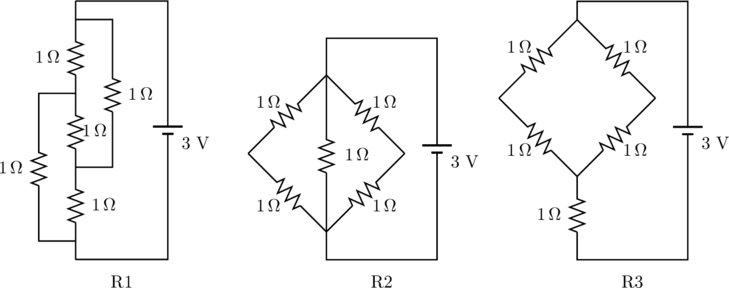
The figure below shows three resistor configurations R1, R2 and R3 connected to 3 \mathrm{~V} battery. If the power dissipated by the configuration R1, R2 and R3 is P1, P2 and P3 respectively, then
Rendered by QuickLaTeX.com

  1. P1 > P2 > P3
  2. P1 > P3 > P2
  3. P2 > P1 > P3
  4. P3 > P2 > P1

Solution

The power dissipated by a resistance network is

(1)   \begin{equation*}   P = \frac{V^2}{R} .  \end{equation*}

The potential applied to all three networks arre the same, so we just need to find the resistances. Of circuits R2 and R3, the latter has a greater resistance since

(2)   \begin{equation*}   % R_3 = 1 \, \Omega + \frac{2 \, \Omega \cdot 2 \, \Omega}{2 \, \Omega + 2 \, \Omega} = 2 \, \Omega ,   R_3 = 1 \, \Omega + \left( \frac{1}{2 \Omega} + \frac{1}{2 \Omega} \right)^{-1} = 2 \, \Omega , \end{equation*}

whereas

(3)   \begin{equation*}   % R_2 = \frac{1 \, \Omega \cdot 1 \, \Omega}{1 \, \Omega + 1 \, \Omega} = 0.5  \, \Omega .   R_2 = \left( \frac{1}{1 \Omega} + \frac{1}{2 \Omega} + \frac{1}{2 \Omega} \right)^{-1} = 0.5 \, \Omega. \end{equation*}

The first circuit can be redrawn in the following way to make the comparison easier.…
Continue Reading

Resistor network with mirror symmetry

JEE Advanced 2012 Paper 1, Question 12

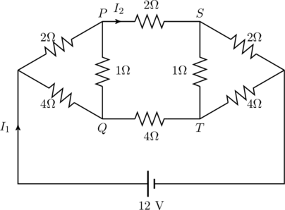
For the resistance network shown in the figure, choose the correct option(s).

Rendered by QuickLaTeX.com

  1. The current through PQ is zero.
  2. I_1 = 3 A.
  3. The potential at S is less than that at Q.
  4. I_2 = 2 A.

Solution

We can speed up the solution by noticing the mirror symmetry of the circuit. Let the current I_1 split into two parts I_a and I_b at the node X (see figure). Similarly, let the currents going into node Y be I_a' and I_b'. If we were to reverse the polarity of the 12 \, {\rm V} battery connected to the circuit, all currents would simply reverse direction, but their magnitudes would remain the …

Continue Reading

Terminal velocity in a magnetic field

A copper connector of mass m slides down two smooth copper bars, set at an angle \alpha to the horizontal, due to gravity (see figure). At the top the bars are interconnected through a resistance R. The separation between the bars is \ell. The system is located in a uniform magnetic field of induction B, perpendicular to the plane in which the connector slides. The resistance of the bars, the connector and the sliding contacts, as well as the self-inductance of the loop are assumed to be negilible. If the connector is released from rest at t=0,

  1. Find the velocty v(t) of
Continue Reading

Missing energy in a rope and a capacitor

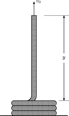
Consider a uniform rope of mass density \lambda coiled on a smooth horizontal table. One end is pulled straight up with a constant speed v_0 as shown.

  1. Find the force exerted on the end of the rope as function of the height y.
  2. Compare the power delivered to the rope with the rate of change of the rope’s mechanical energy.

(This is a problem from chapter 5 of Kleppner and Kolenkow)

Rendered by QuickLaTeX.com

To find the force exerted at the top end, note that if we were to pull up a fixed mass with constant velocity v_0, the total force on the mass should …

Continue Reading

An infinite ladder of resistors

Problem 3.152 of Irodov

The figure below shows an inifite circuit formed by the repetition of the same link, consisting of resistance R_1 = 4.0 \ \Omega and R_2 = 3.0 \ \Omega. Find the resistance of this circuit between points A and B.

Rendered by QuickLaTeX.com

Solution

Let’s denote the resistance between the points A and B by R_{AB}. Since the circuit is infinite, removing the first R_1 and R_2 resistors gives the same arrangement back again — the arrangement is self-similar. That means, the resistance between the points C and D is just R_{AB} without the left-most R_1 and R_2 resistors, and we may redraw the circuit as shown below.

Rendered by QuickLaTeX.com

It is now straightforward to calculate the resistance,

(1)

Continue Reading