JEE Advanced 2019 Paper 1, Question 6
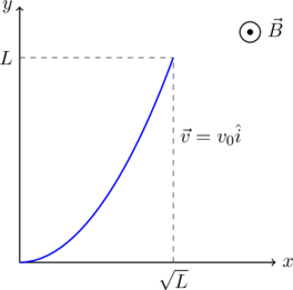
A conducting wire of parabolic shape, initially ![]() , is moving with velocity
, is moving with velocity ![]() in a non-uniform magnetic field
in a non-uniform magnetic field ![]() , as shown in the figure below. If
, as shown in the figure below. If ![]() and
and ![]() are positive constants and
are positive constants and ![]() is the potential difference developed between the ends of the wire, then the correct statement(s) is/are:
is the potential difference developed between the ends of the wire, then the correct statement(s) is/are:

 for
for  .
. for
for  .
. remains the same if the parabolic wire is replaced by a straight wire,
  initially, of length
  .
. is proportional to the length of the wire projected on the
  axis.
axis.
Related Problems:
Electromagnetic induction in a twisted loop
Terminal velocity in a magnetic field
Electric flux through a hemisphere
Discussion
Here is a warm up problem that you can try first. It involves the same basic concept but the calculation is easier:
A thin wire ![]() shaped as a semi-circle of diameter
shaped as a semi-circle of diameter ![]() rotates with a constant angular velocity
rotates with a constant angular velocity ![]() in a uniform magnetic field of strength
in a uniform magnetic field of strength ![]() with
with ![]() parallel to
parallel to ![]() . The rotation axes passes through the end
. The rotation axes passes through the end ![]() of the wire and is perpendicular to the plane of the wire. Find
of the wire and is perpendicular to the plane of the wire. Find ![]() . What happens if AC has an arbitrary shape?
. What happens if AC has an arbitrary shape?
Answer: ![]() . You should be able to find this result without doing any integrals.
. You should be able to find this result without doing any integrals.
Solution
Let us first try to get a physical picture of the given situation. As the wire moves through the magnetic field the electrons in the wire experience a force
(1) ![]()
The force ![]() pushes negative charges toward one end of the wire, leaving the other end positively charged. This goes on until the separated charges themselves cause an electric field
pushes negative charges toward one end of the wire, leaving the other end positively charged. This goes on until the separated charges themselves cause an electric field ![]() such that, everywhere in the interior of the wire,
such that, everywhere in the interior of the wire,
(2) ![]()
Then the motion of the electrons relative to the wire ceases. The potential difference between the ends of the rod is just the integral this electric field,
(3) ![]()
where we have used (2) in the second equation and (1) in the third one. Here, ![]() is an infinitesmal length element on the wire and the integral is computed from one end of the wire to the other. We can plug in the given expressions for
is an infinitesmal length element on the wire and the integral is computed from one end of the wire to the other. We can plug in the given expressions for ![]() and
and ![]() , do some geometry to find the dot product and integrate this expression over the length of the wire to find
, do some geometry to find the dot product and integrate this expression over the length of the wire to find ![]() . However, that method is cumbersome and time consuming. There is a simpler way to find
. However, that method is cumbersome and time consuming. There is a simpler way to find ![]() as hinted in option (D) of the problem.
as hinted in option (D) of the problem.
We begin by recalling Faraday’s law of induction:
If the magnetic field in a given frame of motion is constant in time, then for a loops of any shape moving in any manner, the emf ![]() around the loop is related to the magnetic flux through the loop by
around the loop is related to the magnetic flux through the loop by
(4) ![]()
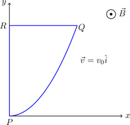
Notice that this applies to loops. In our problem we have an open wire, not a closed loop. So we need to add wires along ![]() and
and ![]() , as shown below, to form a loop.
, as shown below, to form a loop.

Next, we notice that the magnetic field ![]() does not depend on the
does not depend on the ![]() coordinate.
coordinate.
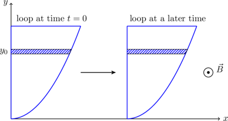
If we consider a thin region inside the loop at some height ![]() (the hashed region in \figref{fig:q6flux}) we find that the magnetic flux through this region is
(the hashed region in \figref{fig:q6flux}) we find that the magnetic flux through this region is ![]() where
where ![]() , is the area of the strip. This flux does not change as the loop slides along in the
, is the area of the strip. This flux does not change as the loop slides along in the ![]() direction. Breaking down the whole area inside the loop into a large number of such thin regions we find that the total magnetic flux
direction. Breaking down the whole area inside the loop into a large number of such thin regions we find that the total magnetic flux ![]() through the loop does not change with time! Therefore the total emf around this loop,
through the loop does not change with time! Therefore the total emf around this loop, ![]() .
.

The emf ![]() is the total change in potential around the loop,
is the total change in potential around the loop,
(5) ![]()
However, using (3),
![]()
since an length element ![]() on the segment
on the segment ![]() is parallel to the velocity
is parallel to the velocity ![]() . Therefore,
. Therefore,
(6) ![]()
where we have used (5) and (3) in the first and second equations respectively. At this point we can conclude that option (D) is correct. Option (C) is also correct since, if we replaced ![]() by a straight wire of length
by a straight wire of length ![]() along
along ![]() , we would get the same segment
, we would get the same segment ![]() if we closed the loop as we have done above.
if we closed the loop as we have done above.
This integral in (6) is easy to evaluate since ![]() and
and ![]() are mutually perpendicular to one another,
are mutually perpendicular to one another,
(7) ![Rendered by QuickLaTeX.com \begin{align*} \nonumber \Delta \phi_{PQ} &= - \int_R^P (\vec v \times \vec B) \cdot d \vec l \\[1em] \nonumber &= - \int_L^0 \left(v_0 \i \times B_0 \left( 1 + \left( \frac{y}{L} \right)^\beta \right) \hat k \right) \cdot (-\hat j \, dy) \\[1em] \nonumber &= v_0 B_0 \int_0^L \left( 1 + \left( \frac{y}{L} \right)^\beta \right) \, dy \\[1em] &= \boxed{ \left( \frac{\beta + 2}{\beta + 1} \right) v_0 B_0 L } \end{align*}](https://www.jeefirst.com/wp-content/ql-cache/quicklatex.com-50ba0cebd90dc396779d47b8d4f25a00_l3.png)
Subsituting ![]() shows us that option (A) is incorrect but (B) is correct.
shows us that option (A) is incorrect but (B) is correct.
The correct answers are (B), (C), (D).